APPLICATION
Introduction
Coating of optical parts is an indispensable process in optical products, which can greatly improve the performance of optical parts, not only improve the accuracy of various optical instruments, but help us improve more excellent digital products as well. Therefore, the requirements for the coating process are getting very high, and the precise control of the film thickness is one of the important parts.
At present, there are many kinds of methods of film thickness monitoring, such as quartz crystal oscillation method, single-wavelength extremum method, wide-band spectrum method and so on. The wide-band spectrum method can provide the film to monitor the irregular film system in a wide wavelength range, while the extremum method generally requires a regular film layer. So, the wide-band spectrum method has been gradually applied to the application of film thickness monitoring system.
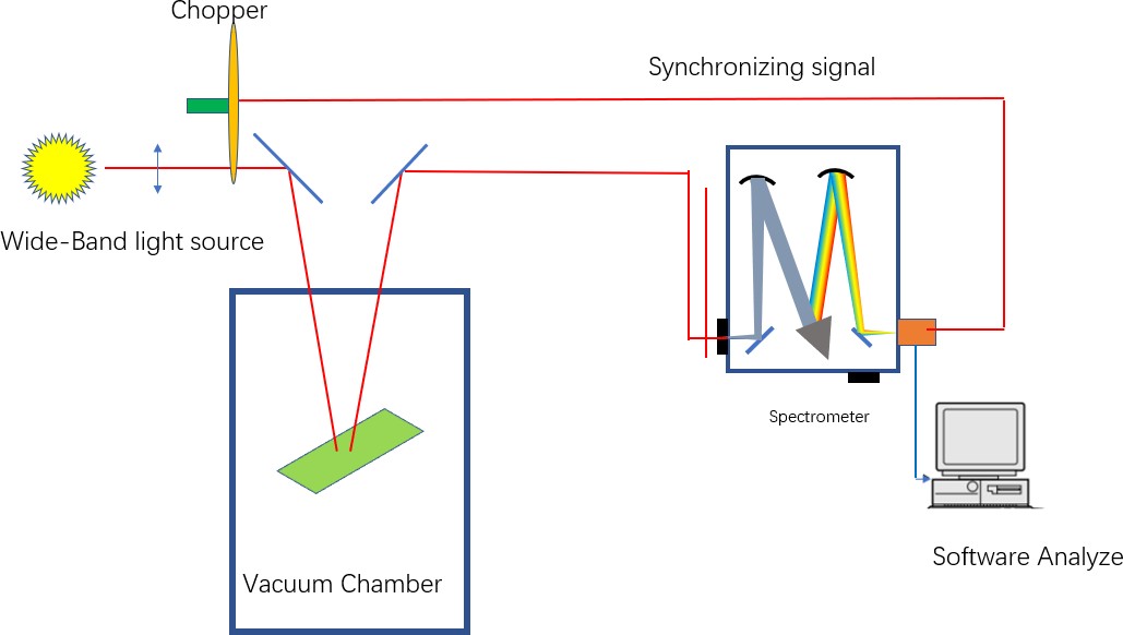
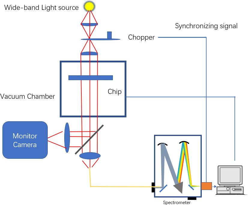
Wide-band spectrum monitoring system often used two kinds of optical path, Vertical path for Transmission way, or Inclined optical path of Reflection way.
Fig.1: Schematic diagram of reflective wide-band spectrum monitoring system
When coating, the inside of the vacuum chamber is a bright environment, the stray light will be measured at the same time when the signal light is received, which will decrease the signal-to-noise ratio(SNR). Therefore, in order to eliminate the influence of stray light, scientists introduced a chopper to modulate the signal light, and at the same time, the chopper output a synchronization signal to trigger the detector.
So there will be two signals: 1, signal light + stray light,
In the monitoring process, the stray light can be effectively removed by subtracting the two signals.
The signal will be received in the grating spectrometer, via Fibre. If CCD is applied after the spectrometer, it’s very easy for us to get a wide spectrum in one shot(even can get several hundred nm)
Fig.1: Schematic diagram of transmission wide-band spectrum monitoring system
Similar to the reflection way, the chopper also modulates the probe light to pulsed light, which is converted into parallel light by the lens group, and the transmission spectrum is obtained after passing through the sample. The probe light is introduced into the spectrometer by optical fiber for analysis. At the other end of the optical path, through the imaging system, the interior of the vacuum chamber can be monitored with a Monitor camera.
We can use CCD as the detector for wide rang capture, or PMT for scanning. These two kinds of detectors has its own advantages, CCD can get wide range spectrum in a short time, while the sensitivity of PMT is much higher, and easy to find the change of weaker signal.
In Recent years, scientists begins to focus on film thickness monitoring in near infrared range.
Fig.3:Schematic diagram of film thickness monitoring system in near infrared range
The spectrometer system and InGaAs detector are used in this diagram. With Labview software, the scientists make a in-situ near infrared film thickness monitoring system.
Zolix provide all kinds of spectrum capturing system, including PMT (for Visible range), InGaAs detector(for NIR range)
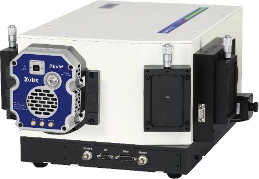
Fig.4:Zolix Spectrometer,PMT and InGaAs Detectors And also we have spectrometer with CCD, Omni-λ3008i-iVacN
Fig.5: Omni-λ3008i-iVacN
resolution(nm) |
0.11@1800 groove; 0.37@600 groove |
Focal Length(mm) |
320 |
相對(duì)孔徑 |
F/4.2 |
Stray Light |
1X10⁻⁵ |
Slit |
0.01-3mm adjustable |
Dimension of grating,mm |
68X68 |
Turrent |
3 |
CCD pixels |
2000×256 |
Size of pixel |
15×15 |
Full capacity |
300,000e- |
Maximum FPS (spectra/s) |
181 |
Readout noise(e,typical) |
3e- |
Dark current |
0.1 e-/pixel/s@-60℃ |
Table 1:Specification of Omni-λ3008i-iVacN
Reference: